
Voltage dividers are a fundamental building block of electronic circuits, and having pre-configured voltage dividers on hand turns out to be very handy for quickly generating known voltage levels from a stable reference, checking and calibrating measurement equipment, and checking instrument signals without overloading test equipment.
Some example scenarios I’ve run into where a bench voltage divider comes in handy include:
- Reducing a line-level signal from volts to millivolts to simulate input from a phono cartridge.
- Reducing a 10V reference to calibration levels like 3V or 300mV.
Rather than building up a janky breadboard divider every time, a few years ago, I built a simple point-to-point set of dividers with a rotary switch and a surplus pedal enclosure.
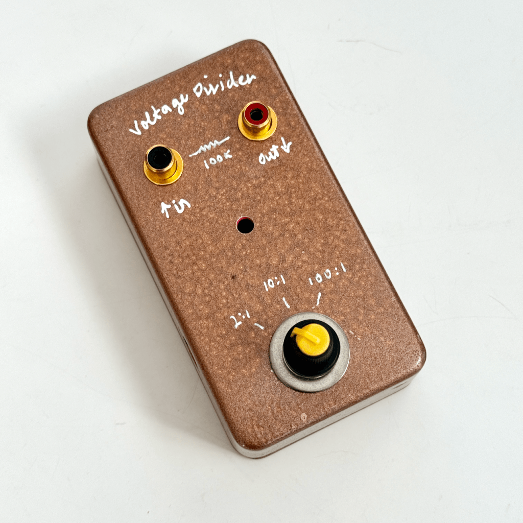
This is pretty okay and gets the job done, but it’s not very precise. Using close-enough standard resistor values only gets in the general vicinity of the target voltage. I wanted something equally convenient and repeatable, but far more precise.
Getting more precise means matching target shunt resistance values within a few ohms. That requires at least the ability to get within a few hundred ohms with one or two standard resistors, then trim out the remainder with a small trimmer potentiometer. And that really calls for a PCB…
The Switchable Voltage Divider PCB
So I fired up Kicad and quickly designed a PCB that implements a switchable resistive voltage divider, each divider tap producing a fixed ratio of the input voltage based on up to two resistors and a trim potentiometer.
Actually there are two PCB designs. The first proof of concept design provided six different resistor-trim-resistor taps. It had no direct switching on board, just taps that could be connected to an external switch. This board was also a bit bigger, probably more suited to a 1590 series or larger enclosure.
The second design is the one highlighted here. It’s smaller, intended to fit in a standard 125B enclosure. It has five separate voltage dividers and pads to fit a 1-pole 5-position rotary switch.
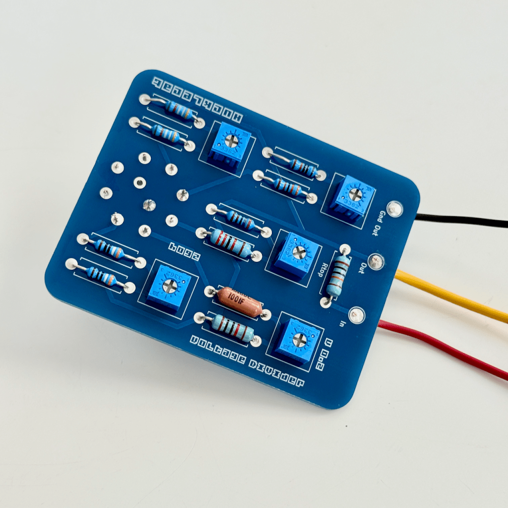
The PCB is designed around a 1-pole 5-position rotary switch (using a 1-pole 8-position form factor) like the ones available from pedal parts supplier Love My Switches or PedalPCB. Each tap has space for two resistors and a trim pot (Bourns 3362P footprint).
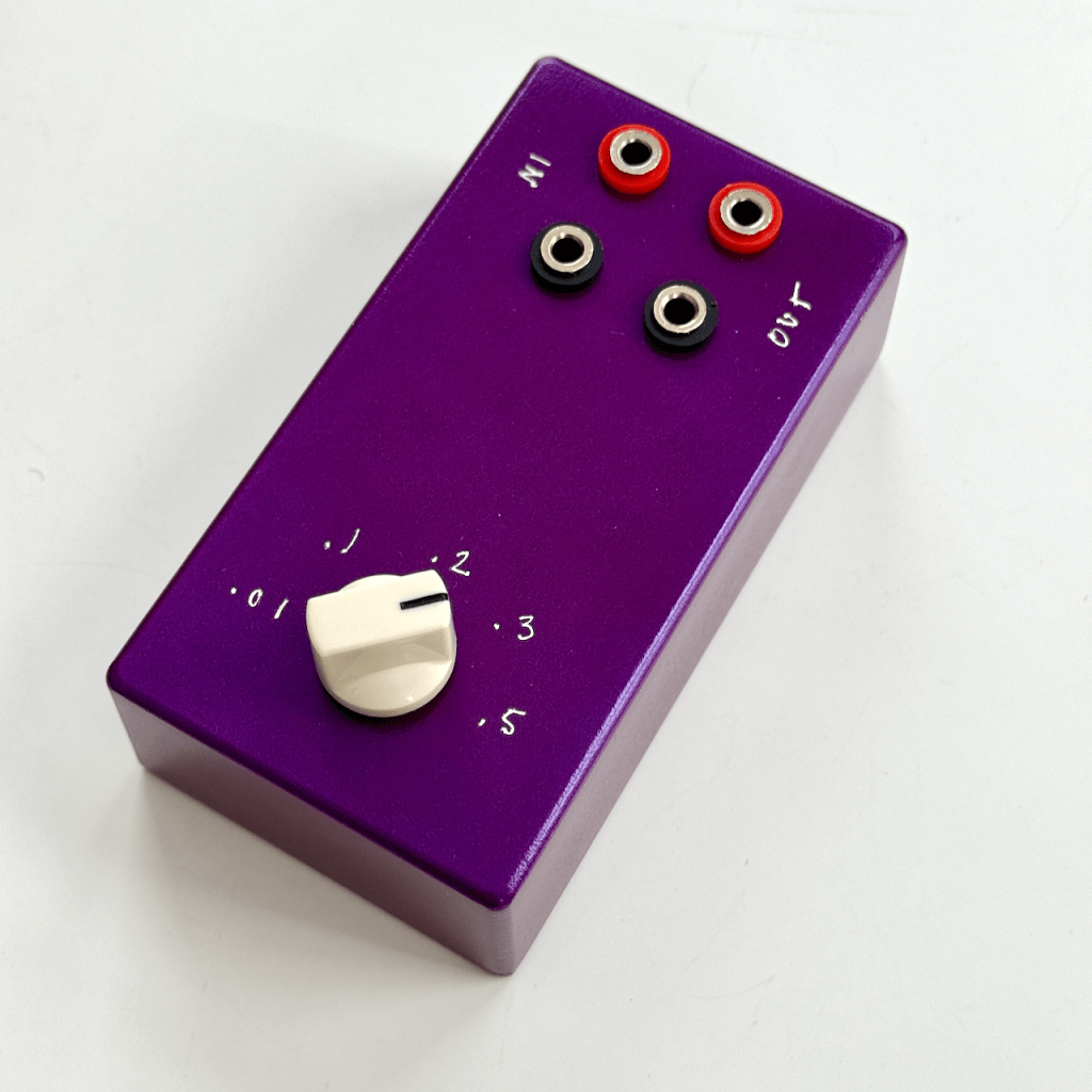
The board is sized to fit within the enclosure with room to install your choice of inputs and outputs (banana jacks, RCA, etc.).
To summarize the BOM I’m using:
- Five Bourns 3362P or equivalent trim potentiometers
- 1-pole 5-position rotary switch (see links above)
- Resistors per your divider details (see below)
- Input and output jacks (your choice)
If you want to build your own, I will have some for sale on eBay. If you are handy with PCB production, you can grab the Kicad or production (gerber) files from my GitHub repository.
Resistor Divider Details
Each tap on the PCB is a two-resistance voltage divider:
Vin ── Rtop ──┬── Vout | Rbottom | GND
Rtop (sometimes designated Rseries or R1) is a fixed value for all taps. I used a 100k resistor in this position that actually measures approximately 100,468 ohms.
Rbottom (sometimes designated Rshunt or R2) is implemented as:
- A fixed resistor
- A small trim potentiometer (Bourns 3362P)
- Optional second series resistor or jumper
This arrangement allows:
- Coarse ratio setting with fixed resistors
- Fine trimming with a low-value trimmer (I used 500 ohm)
- Good long-term stability by minimizing the trimmer’s contribution to total resistance
The rotary switch selects which divider output is routed to the output jack.
Divider Equation
The fundamental voltage divider relationship is:
Vout = Vin * (Rbottom / (Rtop + Rbottom))
To design a divider for a desired ratio:
k = Vout / Vin
Solve for the shunt resistor:
Rbottom = (k / (1 - k)) * Rtop
Example Divider Values
Exact values matter. Let’s say Rtop = 100,468 ohms.
| Divider Ratio | Rbottom (ohms) | Vout from 10V |
| 0.5 | 100,468 | 5V |
| 0.3 | 43,058 | 3V |
| 0.2 | 25,120 | 2V |
| 0.1 | 11,163 | 1V |
| 0.01 | 1,015 | 100mV |
In practice, these are realized using nearby standard values plus the trim pot to dial in the exact ratio.
You can, of course, use whatever ratios you like.
Voltage dividers are pretty straightforward, but it’s not always so simple. Sometimes you need to be aware of source and load impedance, measurement loading effects, power dissipation and self-heating in the resistors, tempcos and long-term stability, and other small but measurable errors, especially when you’re working with precision references or very low output voltages.
Build Notes
Here are some tips for a successful build.
- Measure your series (Rtop) resistor as accurately as you can. Not everyone has a 6.5-digit multimeter to get the least significant digit. The trimmer gives you some wiggle room.
- Do the math or use an online calculator to determine the values for shunt resistances (Rbottom) based on your actual Rtop value. DigiKey has a nice Voltage Divider Calculator.
- Populate fixed resistors first. Use precision metal film resistors where possible. Keep resistor types consistent across all taps to improve ratio tempco matching.
- Install the trimmer (Bourns 3362). Use the trimmer only for fine adjustment. Aim to keep it near mid-range once trimmed.
- Install jumpers or series resistors: if a second resistor footprint is unused, install a jumper. Otherwise, use it to reduce the trim range and improve stability.
- Trim each divider. Apply a stable input voltage. Measure Vin and Vout with the same DMM. Adjust the trimmer until the ratio matches the target value.
It’s a good practice to clean the PCB to thoroughly remove flux residue, especially around high ratios like the 0.01 tap.
Good luck!
